Robotran, a symbolic simulator
In parallel to my Ph.D. research activities, I integrated the development team of the Robotran software. Robotran is a symbolic simulation environment capable of simulating the physical behavior of a given multi-body system.
Most results during my Ph.D. were obtained using this simulator. In particular, the COMAN robot was modeled with Robotran. Such developments are valuable to design and tune the controllers before transferring them to the real platform. My main contributions are summarized below. More information about Robotran can be found on the Robotran website.
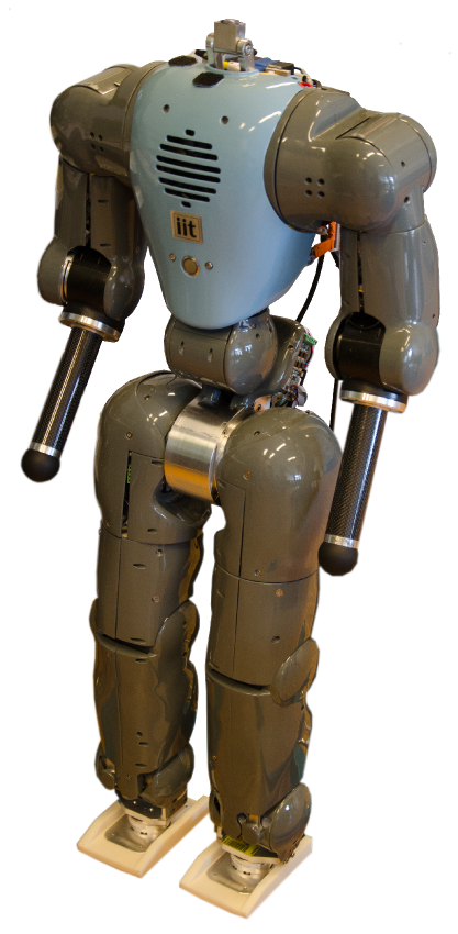
COMAN in reality
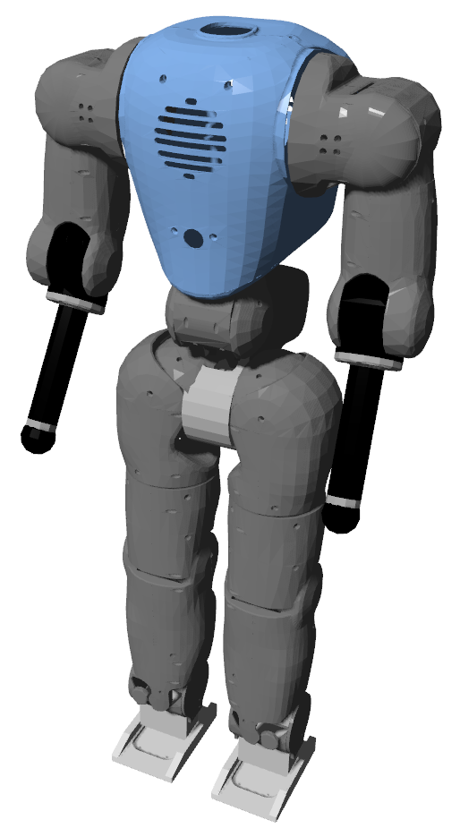
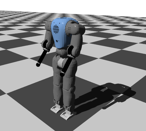
COMAN in simulation
C/C++ features
At the beginning of my thesis, Robotran was mainly developed to run Matlab applications. Only basic C/C++ usage was possible at that time. Below, I present the new Robotran C/C++ features for which I have made a significant contribution.
Project configuration through CMake
C/C++ projects combining different modules and libraries can be difficult to configure, and highly dependent on the operating system. Therefore, a tool capable of automatically building the project on different OS is a valuable feature.
Together with the Robotran team, we developed a tool based on CMake and capable of automatically building and configuring any Robotran project on Windows, Linux and Mac OS. Different options are available to adapt the project according to the user needs, and to the requested features.
Pseudo real-time
Initially, no user interaction was possible during the simulation. More specifically, the process required to fully run the simulation, before extracting the results to analyze them in post-process.
Using the Simple DirectMedia Layer (SDL) library, I incremented Robotran to run the projects in pseudo real-time (i.e. real-time constraints are not guaranteed) while including user interactions using the mouse, the keyboard or a joystick.
Some default commands are implemented in any project, but the user can increment them with its own commands. This is potentially relevant to control a robot in real-time. It is also possible to adapt the simulation time, by slowing down the simulation speed, speeding it up (up to the CPU limits), or temporarily stopping it.
Signals temporal evolution
Extracting various signals (joint positions, torques, custom controller variables...) is an important feature of most projects. Therefore, I developed a new tool (also using the SDL library) to visualize the evolution of any signal in real-time (i.e. their value being displayed and updated in real-time).
During the simulation run, the 3D animation and the signals temporal evolution are recorded. After a break in the simulation run, it is therefore possible to visualize the past motion and the related plots.
During a break, different graph manipulations (zooming, translation) can be done, using the mouse or the keyboard (or a combination of both). In particular, automatic graph scaling features can be activated to improve the signals legibility.
OpenGL 3D visualization
Initially, the only possibility to visualize the 3D animation resulting from a simulation was to use a graphical Pad, including a post-process visualization tool based on a Java framework. This tool is now integrated in the C/C++ projects, in order to be used during real-time simulation runs.
However, this Java tool is quite outdated and has some compatibility issues, especially with the latest versions of Mac OS. Therefore, I developed a new 3D visualization tool based on the OpenGL API.
This new 3D visualization tool can represent any multi-body system, by computing the absolute position and orientation of these bodies at each visualization frame. This OpenGL visualization can be configured, in order to adapt its available features to the computer capabilities, mainly dependent on the graphics processing unit (GPU). In particular, different shaders can be selected.
basic shader
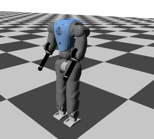
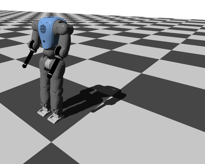
shader with lights
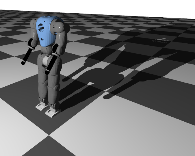
shader with lights and shadows
It is also possible to control the viewpoint (camera) and its related projection (perspective or parallel). Finally, different lights (directional, point and spot lights) can be combined.
directional light
point light
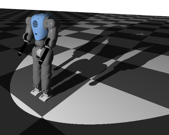
spot light
Simulation features
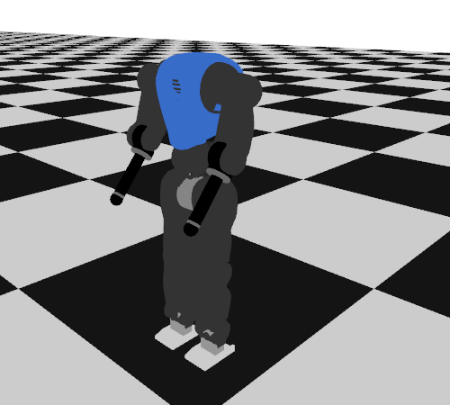
In the video below, an example of a simulation is presented to illustrate some of the simulator features. This is tested with COMAN walking in a 2D scenario (i.e. no lateral degree of freedom).
Student projects
During my Ph.D., I supervised the projects and practical sessions of different courses (both at UCL and EPFL). In particular, I developed projects for the students using the Robotran simulator features presented above. This was mainly done for two courses: Introduction to robotics (LMECA2732, UCL) and Mobile robots (MICRO-452, EPFL). Some results are presented below.
LMECA2732 project (UCL): Eurobot 2014 map
LMECA2732 project (UCL): Eurobot 2015 map
LMECA2732 project (UCL): Eurobot 2016 map
MICRO-452 project (EPFL): custom map
Most of these projects where related to the Eurobot competition, an international amateur robotics contest where two teams of robots had to compete to fulfil a variety of objectives. I personally participated in the 2012 edition of this contest, as illustrated below.